Simulations
Fluid Dyanamic and Thermal Simulaitons
The fluid dynamic and thermal simulations of Rimor S.r.l. were born to define new concepts of construction and management of flows both in the machines, in the chambers, and in the field of blowing, heating, cooling to obtain precision in the heating chambers, an interior of heating chambers.
The simulation can predict physical behaviors,therefore, it can validate and test the engineering calculations of Rimor S.r.l.
The engineering performs calculations, and the software does the tests, giving the designer an immediate opportunity to understand the effect of his invention.
The simulation office of Rimor S.r.l. provides internal services at the service of the designers present in the company but can do the same service for customers who need to perform fluid dynamic and thermal simulations.
Validating new insights without risking expensive tests during testing, minimizing the final test phase that can still be performed, verifying the possibility of new technologies are the objectives that fluid dynamics simulation manages to achieve.
The quality of Rimor S.r.l. is precisely that of obtaining reliable and safe results, setting the simulation correctly and effectively.
The computational fluid dynamic simulation is based on mesh, therefore with ever greater precision increasing the software calculation load. In addition, the system can be set up in different ways according to the client’s objectives.
The computational fluid dynamic simulation requires highly advanced professionals and machinery to generate precise calculations without uncertainties.
All Rimor S.r.l. machines have been studied through computational fluid dynamic simulation, with remarkable results. The patents of Rimor S.r.l. are derived from fluid dynamics simulation. Rimor S.r.l. has been using computational fluid dynamic simulation systems for ten years to solve their problems and those of our customers.
The charging fees of Rimor’s computational fluid dynamic simulations are competitive, but above all, the experience is at customers’ service to quickly give high-level results.
Attachments
Markets
Features
Applications

Cooling or heating of the item fluid
Fluid Dyanamic and Thermal Simulaitons
Different heat treatments and other processes become necessary to change the parts’ temperature to obtain chemical or physical derivation results. Evaporation, cooling, physical modifications of materials, and transformations of the molecular structure are achieved by changing the temperature in a controlled way.
The piece is physically positioned inside the simulator and hit by airflow or a liquid flow. The software calculates the finite element heat exchange and predicts the heating curve, i.e., the temperature of the individual elements that make up the piece.
The display is able, through the pointer, to determine exactly the temperature of each particle in a precise way.
The piece can then be transferred from one behavior to another, first hit by a moving flow, then by a stationary flow, or by a variable flow.
In addition to the heating and cooling of the piece, the heating or cooling behavior of the fluid affecting the piece can also be predicted.
This is in order to determine at what temperature the fluid could be located as well as the particular physique to be treated.
Attachments

Uniform blowing on hoods and nozzles
Fluid Dynamic and Thermal Simulations
The nozzle is usually used in multiple heating or cooling applications. The so-called air knives are applied, for example, in the printing and converting sector, in the lamination sector, in the coating sector or the rotogravure sector, or the flexography sector.
The blowing groups are therefore often used to carry out processes which therefore require a high blowing precision.
The blowing can be used for heating and to dry or remove liquid particles.
In any case, air can also be blown at 80/100 m / s using industrial fans. Therefore, the blowing knives are used at different operating speeds, but it is certainly necessary to obtain the maximum efficiency of the nozzle.
In addition to the uniformity study, the study of air outlet is determined to obtain a heat exchange or a certain behavior of the air that it exchanges with the film or with the sheet or coils to be treated.
The uniformity of the rimor nozzles and hoods are then usually obtained without pressure drops.
This aspect is crucial as it is usually easy to obtain uniformity by inserting pressure drops inside the hoods; rimor quality can design and build hoods and nozzles without pressure drops to achieve uniformity of flows.
Attachments

Suction on hoods
Fluid Dynamic and Thermal Simulations
The suction on the hoods is used both downstream of a blowing system to recover the air blown through the nozzles: the importance of suction in a uniform way is a feature that allows not to have a predominance of flow in one part but a ‘high uniformity in order not to have disturbances in the case of films.
The aspiration of the extractor hoods serves to predict the distance at which the hood will be able to aspirate.
That is, for example, essential when designing exhaust hoods which are mobile systems that are used in roller benches or automotive test and test benches.
Another sector where it is essential to study the behavior of hoods in case of aspiration of polluting gases, such as crowns that are inserted above treatment tanks.
Another fundamental principle of suction is the suction hoods of the painting areas or sandblasting sites.
The suction hood is also placed on the heat treatment areas of the pieces or areas where smoke or pollutants are generated.
Certifying such treatments and such behaviors allows to coherently protect the working staff and the area affected by the processing.
The capture capacity of a suction front depends on both the suction speed and the size of the suction area, and the suction slots. The fluid dynamics calculation and the simulation allow to maximize this phenomenon by dimensioning the suction front, the speed, and the air distribution.
Attachments
")
Flow definition in chambers: Push Pull Systems
Fluid Dynamic and Thermal Simulations
The definition of the flows in the chambers is used in common situations: aspirating and conveying a pollutant into a chamber. That can be applied for example, in Camit and Rimor sandblasting and painting cabins: in this case, Rimor designs natural or forced intake systems ( Push-Pull) where the air is conveyed in the correct direction without incorrectly affecting the operator.
Rimor-Camit uses these computational fluid dynamic simulation systems to overcome pollution in painting or sandblasting plants. The flows enter and leave the chamber through well-defined inlet openings and are then conveyed to the outside through many exits designed to ensure a flow always Up down (from top to bottom) with certain and safe work situations.
The other macro area where the definition of flows in the chambers is used is the heating chamber, where, for example, it is necessary to heat the paint in drying or the powder paint in cooking or to heat the PREPREG carbon for boats and deckhouses, boats and yachts or various kinds of reheating heat treatments such as Rilsan or low temperature heat treatment chambers (for the furnace part see the particular division of simulation into heat treatment furnaces).
Rimor can also determine the correct flow when it is required to define a cooling heat treatment or conditioning at a controlled temperature and atmosphere.
Rimor study and calculation system is also effective even in cases where it is not a large but small chamber, in case it is also necessary to provide the calculation inside a small heating furnace or a small chamber of heating.
Attachments

Gravimetric separation
Fluid Dynamic and Thermal Simulations
Gravimetric separation is used in all those cases where it is necessary to precipitate a solid body or divide two bodies (one light from one heavy) present in a fluid, be it air, water, or other fluids.
It is possible to define the kinetic behavior of the solid body by predicting how much of this kinetic energy is released into heat during the journey.
A typical application is the cyclone, wind sifter, static air separator, or chamber where a path is defined, and a specific contact is obtained between the solid body and the separator.
Even without this contact that accelerates the loss of kinetic energy, Rimor’s computational fluid dynamic simulation and finite element study can predict the effect of the simple gravitational attraction in separators or in throwing materials.
Rimor can study separator cyclones or other separation systems and geometries, providing the gravimetric curve and, therefore, the percentages of residual material after the separator divided by particle size.
The design system of the finite element rimor is also applied to Camit in the study of filters and systems where the precious pre-chambers of the rimor allow to maximize the life of the filters.
In addition, the washing chambers are also studied where the physical components are separated inside the chamber.
The gravimetric fluid dynamics simulations are also important to obtain a result in the separation of the bodies following the shredding in the recycling and recovery plants of cars or plastic in the various processes.
Attachments

Definition of flows in piping
Fluid Dynamic and Thermal Simulations
In order to convey the air flows it is often important to use complex or simple piping geometries where the connection slings or the suction plenums must be made to respect the environments where the systems are installed and obtain performance.
The definition of the flows in the pipes can take place both to be sure that the transported material does not deposit; this happens in pneumatic transport systems or transport systems in general. In fact, in pneumatic transport or air transport of materials, the transported material must always remain above the support speed, meaning the minimum rate at which the material remains suspended within the flow. The computational fluid dynamic simulation allows not to have areas where the material is deposited inside the pipeline or in correspondence with fittings.
The second case in which it is necessary or preferable to study the flows inside the pipes is, for example, the reduction of pressure drops in correspondence with connection branches or plant geometries. In this case, the definition of the minimum pressure drops allows to obtain excellent results.
Another section where the behavior of fluids inside the pipes is studied through the computational fluid dynamics simulation is, for example, the conveying areas between the machines and the user understood as blowing systems or cooling beds.
Attachments

Definition of pressure drops in plants
Fluid Dynamic and Thermal Simulations
The defining theory of pressure drops in plants starts from practical experiences where the classical geometries within the machines and piping systems have been studied. The various geometries were then defined through defined graphs and tables.
The advent of new calculation systems and fluid dynamics simulation allow to obtain significant results with the direct calculation of the geometries, thus reducing the calculation error of traditional calculation systems.
By managing to define the head losses using the fluid dynamics simulation, the most important results are obtained for new geometries not traditionally studied, and precise measurement is obtained regarding the classical geometries studied in the past.
The computational fluid dynamic simulation also allows to optimize the pressure variation inside the systems in suction from several points or several suction branches, allowing better management of the constant pressure plant systems, controlled by inverters: the closing or opening of the various branches involves a variation in pressure or depression which is compensated by the variation of the revolutions following the measurement of the same pressure in the common branch.
The correct sizing of the common parts of the systems with various pressure or depression branches allows to obtain the right behaviors that comply with the regulation criteria.
Attachments

Definition of flow behavior in machines
Fluid Dynamic and Thermal Simulations
The definition of the flows inside the machines allows to obtain the correct performance of complex machines and at the limit of understanding. Only thanks to the potential of fluid dynamics simulations it is possible to obtain the safety and certainty of having a guaranteed yield.
Fans are machines sized and correctly certified ERP, but when designing ventilation machines, the circuits become more complex, including, for example, industrial burners or heat exchangers or air/air heat exchangers, there may be hidden pressure drops or no determined that can also generate instability and not have the safety of pressure drops and therefore not be able to guarantee the performance curve to the user.
In some machines such as the Recube, which are ventilation machines with both soundproofing systems and heat exchange and regulation systems onboard, it is important, for example, to manage the flows in or out of the vein, so for example that a certain type of air does not affect the burner: this detailed view is achievable with fluid dynamics simulations.
Furthermore, the simulation allows you to certify ventilation machines with multiple fans on board that exchange flows inside the machinery.
Plenum, distribution on heaters, valves, and what can be inserted inside the machinery can be coordinated and managed through fluid dynamics simulation to obtain maximum system performance.
Attachments

Valves behavior
Fluid Dynamic and Thermal Simulations
Valves are physical elements that create a static leak in systems. Multiple types of valves are used, such as butterfly valves, square wing valves, or DAPO valves,
In particular, in valves, the physical movement of the shaft determines a certain ability to generate a leak. It is, therefore, possible to create an adjustment graph with the perfect correlation between the valve position and the relative pressure drop.
This study allows, for example, defining the accuracy obtainable from a system with valves and defining the correct diameter of a valve for a specific application.
Finally, it is also possible to determine the different behavior of different valves: depending on the type of valve, whether with flaps or plate, different regulation curves can be obtained, and in other areas of the movement range of the valves themselves.
The handling system must be defined and regulated in this way to achieve compliance with the needs of the system (in the sense that every single minimum movement generates a loss of load to the system and the precision of the handling system can thus be uniquely defined without uncertainty.
In the case of choosing the type of valve, for example, being able to compare a valve with a butterfly plate or a dapò, with many wedge-shaped fins that move simultaneously, we can easily define the difference in behavior of the various valves, thus choosing the right and cheapest type.
Attachments

Uniformity in industrial heating furnaces
Fluid Dynamic and Thermal Systems
The heating furnaces require a certain temperature uniformity and a certain performance in terms of airspeed and temperature. To obtain uniformity of heating inside the furnaces, it is necessary to define the flow that crosses the heating chambers, the behavior of the heating system, whether indirect or direct, and the situation obtained thanks to a heating system is defined as finite elements.
Each heating system, be it a burner or an indirect exchanger, causes a certain heat transfer towards the recirculated flow in the furnace. This behavior can be defined in detail to obtain a uniform flow in temperature and speed. Having a uniform flow in both temperature and speed can ensure uniformity inside the heating furnace.
The definition of fins or paths in the furnace, as well as the definition of the profiles at the outlet of the centrifugal recirculation impeller is a subject that rimor makes both to be sure that its ventilation machines are correctly used in the furnaces, and to be safe that customers’ construction ovens can have a correct performance in terms of temperature and speed.
The furnaces can be designed with chambers with well-defined internal paths or free with agitators placed on the ceiling or the side. In both cases, the correctly used fluid dynamics simulation allows us to predict the results that can be obtained in the furnace.
Attachments

Film and sheet heating or cooling
Fluid Dynamic and Thermal Simulations
The heat exchange on film or plate is an application often used in fields such as the coating of coils or any process that requires the plate or film to be brought to a certain temperature by jets or blowing hot air or cold air or refrigerated air through exchangers.
The fluid dynamic simulation of the rimor can generate excellent results by guaranteeing a definition result of the number of nozzles or their speed. The study is applicable in various fields such as rolling or painting the coils or cooling the coils themselves.
The determination of the behavior of the slab foresees being able to verify the effect of the heating caused by a jet of air conveyed on the piece or the moving sheet.
The study can also determine the effect of the distance from the nozzle and the behavior of the outgoing flow from the nozzle depending on its conformation.
An interesting part of the simulation is the flow exiting the hood and its heat exchange and behavior effect.
Attachments

Quenching tanks behavior and re-circulation fans usage
Fluid Dynamic and Thermal Simulations
The study and behavior of quenching tanks is a particular application of finite element fluid dynamics simulation. The study plans to define the behavior of the heat exchange fluid. The importance of computational fluid dynamic simulation allows it to be particularly noted in avoiding the phenomenon of air bubbles, which, by creating thermal insulation, does not allow a correct internal molecular transformation of the body to be tempered.
Quenching is a controlled cooling of a metal component that allows for a particular molecular transformation.
At the same time, any treatment involving immersion in a tank requires agitation, which, if it is not as delicate as in hardening, becomes an improvement in the areas where the tank is made to perform cooling.
Rimor produces high-efficiency agitators with marine propellers driven by long shaft electric motors with variable speed and supported by elements that allow easy disassembly in the tank. To define the best position of these field elements, the fluid dynamic simulation of the rimor allows to predict the effect of these agitators inside the tank to affect the entire tank correctly.
Attachments

Behavior con heat exchnagers, recuperators and combustion chambers
Fluid Dynamic and Thermal Simulations
The behavior of the exchangers allows to obtain an optimization result of the exchanger or the combustion chamber. The exchanger is a hot or cold body that exchanges heat with the fluid that touches it.
The heat transfer coefficient can then be determined both theoretically and more precisely through fluid dynamics simulation.
First of all, the correct flushing system is determined thanks to which the rimor guarantees 90% accuracy, having a deviation from the theoretical average of 10% only in each point of the exchanger.
The other important part is to determine the correct heat exchange by adequately defining the logarithmic mean temperature, i.e., the achievement of the two points of thermal jump of fluid one and fluid two.
The function of heat exchange systems is to generate a hot flow and generate a cold flow, exchanging with a fluid at a different temperature via a heat exchange surface.
Creating proper flows allows to maximize the exchange surface and generate a correct and coordinated temperature jump to always keep the exchange flow with the hot or cold body at a certain temperature difference.
Obtaining the correct flushing of a heat exchange system also allows to maximize the duration by reducing the fouling of the heat exchanger.
Attachments

Venturi and Benoulli Behavior
Fluid Dynamic and Thermal Simulations
The Venturi system is based on the acceleration of a compressible fluid such as air which, passing through a reduced section, accelerates when the dynamic pressure exceeds the total pressure, thus bringing the static pressure to negative. Each gas, like air, has three energy components, static pressure, dynamic pressure, while the geodetic component becomes negligible (while for liquids, it becomes important). In a system where the air is accelerated, the sum of the two main elements is conserved due to the conservation of energy.
In particular, Rimor’s computational fluid dynamic study transforms this concept into physical machinery, with solutions that exploit this phenomenon to generate aspirations, particularly in the trimming suction systems and in the suction of hot gases. The system can then be exploited to generate and induce secondary fluids with a primary fluid. The behavior of the Venturi and Bernoulli succeeds in giving a particular plant shape to the Rimor machines and the cleaning systems of the counter-current filters.
The execution of the machinery respects the best performance of the Venturi systems and is easily applied both with Venturi systems with the central flow and with the crown flow.
Attachments

Definition of flows in helicoidal fans: rectifier and pre-distributor
Fluid Dynamic and Thermal Simulations
The helicoidal fan represents a very effective ventilation system, especially for significant flow rates and low or medium pressures. The helical fans can generate significant flows in small spaces. There are many applications for helicoidal fans.
In particular, they are frequently used in flow generation applications for car tests or to ventilate heat exchangers. In both cases, it is essential to generate a uniform flow with high accuracy.
This behavior can be obtained by inserting blades before the fan, thus defining and designing pre-distributors or inserting vanes called post-distributors.
In the first case, the flow on the blades of the helical fan is pre-directed, obtaining a higher pressure with the same rotation, while in the second case, with the post distributors, a non-rotating flow is obtained.
Finally, it is possible to study the two-stage system with counter-rotating helical fans where two impellers are rotated in the two different rotation directions, thus obtaining a pressure higher than the single-stage, for example, in tunnels or road works or mining excavations.
Attachments

Film support and Coanda effect sheets
Fluid Dynamic and Thermal Simulations
The film support, the so-called Coanda effect, or generally the support of a body through a flow, can be studied by Rimor with computational fluid dynamic simulations.
Basically, instead of having a film supported by a mechanical system of rollers, the force of air is used on the film or the sheet coil to be able to float the film or the continuous sheet and at the same time generate a cooling effect but more particularly of heating the film.
Different blowing and support systems are possible, often used in so-called floating furnaces where the material is made to float supported by a series of flows.
One of these systems is the Coanda effect, where two flows converge towards the center being inclined and create a particular ‘recycle’ of air that can also support bodies of a certain weight.
On the other hand, other systems perform using spaced vertical flows that generate support for the film or coils.
Rimor simulates the correct outlet and geometry of the nozzle to ensure sufficient force to support the film that is made to pass inside the heat exchange and blowing box.
The system can also operate vertically, with two series of blowers that convey the air in the center, keeping the film or coils in balance in the center of the exchange tunnel.
Attachments
Attachments
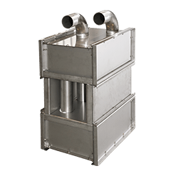
Heating systems
and heat exchangers
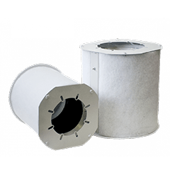
Industrial
fan silencers
Control
accessories
Joints and
anti-vibration systems